Start with the cooling-system duty. Define every interface around it.
Position feedback and electrical connections need a clearly identified equipment role, operating environment and qualification basis.
Cooling-water installations contain valves, actuators and associated instrumentation. A position switch may provide a defined travel indication, while a cable assembly carries that signal to a junction point or control input. The physical connection is only one part of establishing suitability.
For a nuclear-site enquiry, the system classification and procurement requirements need to be identified at the outset. A component used elsewhere in industry cannot be assumed suitable for a safety-related duty simply because its dimensions or nominal electrical rating appear to match.
Choose the feedback your equipment needs.
For nuclear cooling systems, start with the task below. These routes narrow the product search; the final configuration is reviewed against your installation and operating conditions.
Confirm a defined position
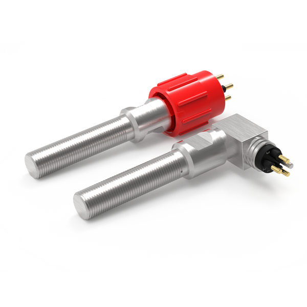
Review non-contact proximity switching for an open, closed, home or engaged indication.
Resolve together: Target geometry, sensing gap, mounting and required contact state.
Compare proximity switches ↗Detect physical actuation
Where a cam or moving feature can press a plunger, review a mechanical limit switch as another sensing method.
Resolve together: Operating force, travel, overtravel and a separate mechanical stop.
Explore mechanical limit switches ↗Connect the sensing point
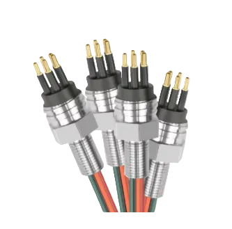
Define the lead between the sensor and equipment interface, including any movement and maintenance access.
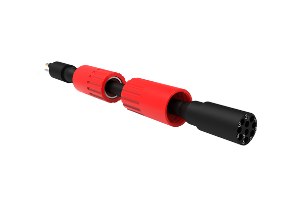
Resolve together: Mating parts, pin allocation, cable length, routing and end termination.
Explore cable assemblies ↗Where each component fits.
Indicate an agreed valve or actuator position.
A switch can provide discrete feedback at a defined point in the mechanism’s travel. The required function, target arrangement and electrical behaviour need to be documented alongside the installation conditions.
- Position indication and contact state
- Mounting geometry and access for inspection
- Specified environmental and functional requirements
Define a controlled equipment interface.
Where a separable connection is permitted by the project design, the connector becomes part of the specified electrical assembly. Materials, sealing, identification and inspection requirements should be reviewed with the responsible engineering team.
- Permitted connection and termination method
- Interface identification and pin allocation
- Materials, inspection and qualification evidence
Carry the signal within the defined installation.
Cable selection depends on its duty, route and environment. The project may specify temperature, moisture, ageing, radiation or fire-related requirements; the applicable requirements must be provided rather than inferred from a generic cable description.
- Conductor, insulation and jacket requirements
- Routing, termination and support details
- Required records and acceptance testing

Example: an enquiry for a cooling-water valve assembly
Begin with the valve duty, system classification, installation environment and governing procurement specification. That allows the engineering review to establish whether a proposed switch and cable arrangement can be considered, and what evidence is required before an offer is made.
Contact us ↗From the equipment to the input.
A typical functional path. The final arrangement depends on the equipment and project specification.
- 01
Mechanical state
The valve or actuator reaches a defined position.
- 02
Position indication
The switch presents the specified contact state.
- 03
Electrical assembly
Cable and any permitted connector carry the signal.
- 04
Receiving interface
The project control or monitoring input receives it.
The details to resolve together.
Identify the classification first
State whether the equipment has a safety-related function and provide the relevant project requirements. Suitability cannot be inferred from a general application page.
Review the complete assembly
The switch, cable, connector and terminations must be considered together where qualification or environmental evidence is required.
Keep changes traceable
Confirm documentation, material controls, inspection, replacement and change-control requirements with the project’s responsible engineering team.
Bring the installation into the brief.
Share what you have. A drawing, an existing part reference or a description of the operating requirement is a useful starting point.
Contact us ↗- System duty, equipment classification and procurement specification
- Environmental conditions and qualification requirements
- Mounting, wiring and permitted connection arrangement
- Inspection, traceability and acceptance documentation
No nuclear safety qualification or approval is implied for the DepthLink catalogue. Any proposed supply is subject to a project-specific suitability and evidence review.
See the complete connection.
Explore how DepthLink position switches, underwater cable assemblies and custom equipment interfaces work together. Contact our team to discuss your installation.
Explore system engineering ↗