
Connect the local sensing point to the wider subsea system.
Production equipment combines mechanical movement, instrumentation and control. The local electrical interfaces need the same attention as the main equipment.
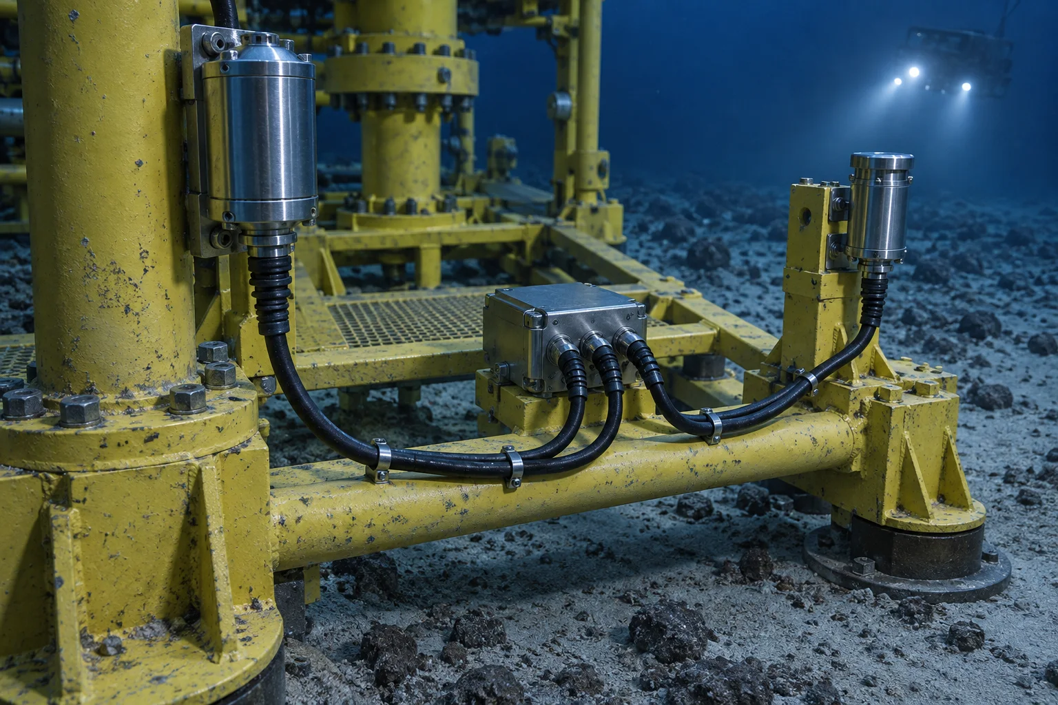
Subsea trees, manifolds and associated equipment bring together valves, actuators and instruments within a demanding installation envelope. Local sensing and electrical connections support the exchange of information between those components and the control system.
DepthLink’s application discussion starts at the component interface: what needs to be sensed, how the signal leaves the equipment and where the assembly connects next. Defining that local scope helps the project team align mounting, cable routing, connector selection and supporting documentation.
Choose the feedback your equipment needs.
For oil & gas production, start with the task below. These routes narrow the product search; the final configuration is reviewed against your installation and operating conditions.
Confirm a defined position
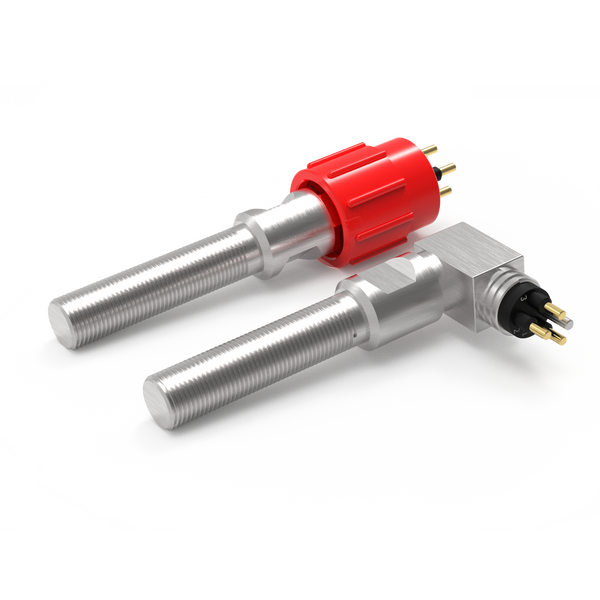
Review non-contact proximity switching for an open, closed, home or engaged indication.
Resolve together: Target geometry, sensing gap, mounting and required contact state.
Compare proximity switches ↗Detect physical actuation
Where a cam or moving feature can press a plunger, review a mechanical limit switch as another sensing method.
Resolve together: Operating force, travel, overtravel and a separate mechanical stop.
Explore mechanical limit switches ↗Connect the sensing point
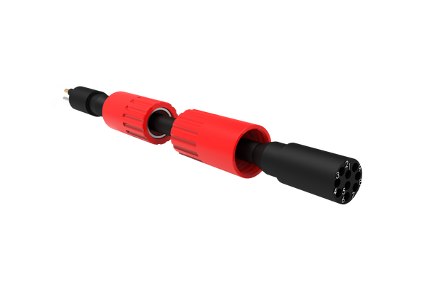
Define the lead between the sensor and equipment interface, including any movement and maintenance access.
Resolve together: Mating parts, pin allocation, cable length, routing and end termination.
Explore cable assemblies ↗Where each component fits.
Provide local position indications.
Switches can be considered for defined valve, actuator or mechanism positions. The sensing target and mounting arrangement should be reviewed alongside the control-system signal requirement, rather than selecting a switch on size alone.
- Valve and actuator end-position feedback
- Target alignment within the equipment frame
- Contact logic at the receiving input
Define equipment and module boundaries.
Connectors provide interfaces between local devices, harnesses and distribution or control equipment. Connection method, access and the intended retrieval strategy influence the choice of interface.
- Equipment-side and harness-side references
- Required mating environment and tooling access
- Pinout, keying, materials and sealing arrangement
Link the distributed equipment.
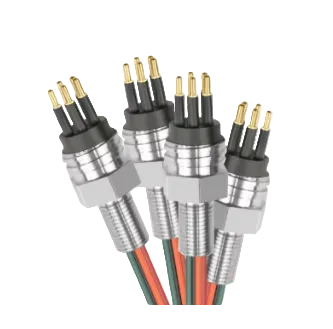
Short local leads and multi-branch harnesses can carry signals between sensing points and junction interfaces. Cable support, branch orientation and protection against handling loads belong in the assembly specification.
- Single-ended, double-ended or branched format
- Conductor, shielding and termination requirements
- Routing, restraint and installation identification
Example: replacing an existing sensor lead
A useful replacement brief includes the part references at both ends, the wiring schedule, cable length and installed route. A similar-looking connector is not enough to establish a match: the precise mating interface and electrical allocation still need to be checked.
Contact us ↗From the equipment to the input.
A typical functional path. The final arrangement depends on the equipment and project specification.
- 01
Sensing point
A switch indicates a defined equipment position.
- 02
Local harness
The signal follows a supported cable route.
- 03
Distribution interface
A connector links the assembly to the next module.
- 04
Control system
The wider system receives and uses the indication.
The details to resolve together.
Pressure applies to the assembly
Agree the operating environment and test scope for the complete terminated assembly, including its seals and interfaces.
Design for installation and retrieval
Consider how the lead is handled, where it is restrained and whether the intended connection can be reached using the planned tooling.
Agree the document package
Identify required drawings, wiring schedules, material records, inspection results and traceability before the supply scope is finalised.
Bring the installation into the brief.
Share what you have. A drawing, an existing part reference or a description of the operating requirement is a useful starting point.
Contact us ↗- Equipment function and system interface drawing
- Existing connector references and wiring schedule
- Pressure, temperature and exposed environment
- Quantities, delivery needs and project documentation
The application overview describes potential interface roles. Project-specific qualification, compatibility and supply scope must be confirmed for the selected equipment.
See the complete connection.
Explore how DepthLink position switches, underwater cable assemblies and custom equipment interfaces work together. Contact our team to discuss your installation.
Explore system engineering ↗