Subsea Position Switches for Ocean Research Equipment
Discrete position feedback for underwater research samplers, docking mechanisms and deployment locks, with serviceable signal connections.
Ocean research instruments can include sampling mechanisms, deployment locks and docking interfaces that need local position feedback. A compact underwater switch can report a defined mechanical state to the instrument controller.
That state should be described precisely. Detecting a sampler at its closing position does not independently prove that a sample was retained or a seal is sound. The sensing assembly supports the wider instrument design and its validation process.
Choose the feedback your equipment needs.
For oceanographic & research equipment, start with the task below. These routes narrow the product search; the final configuration is reviewed against your installation and operating conditions.
Confirm a defined position
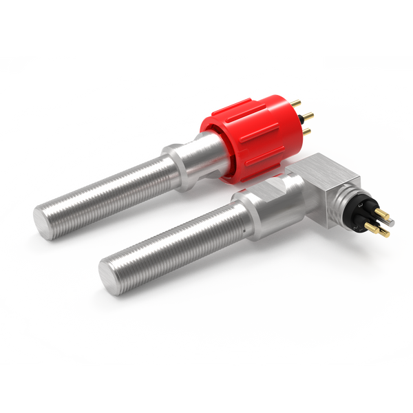
Review non-contact proximity switching for an open, closed, home or engaged indication.
Resolve together: Target geometry, sensing gap, mounting and required contact state.
Compare proximity switches ↗Detect physical actuation
Where a cam or moving feature can press a plunger, review a mechanical limit switch as another sensing method.
Resolve together: Operating force, travel, overtravel and a separate mechanical stop.
Explore mechanical limit switches ↗Connect the sensing point
Define the lead between the sensor and equipment interface, including any movement and maintenance access.
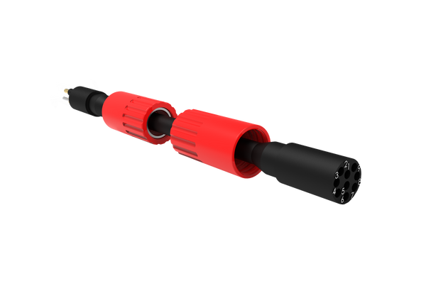
Resolve together: Mating parts, pin allocation, cable length, routing and end termination.
Explore cable assemblies ↗Where each component fits.
Detect the defined mechanical position.
Review space, target approach and controller input requirements. Provide maximum deployment pressure and temperature at the sensing point.
- Sampling mechanisms
- Instrument docking
- Deployment locks
Make the service interface practical.
Match the instrument’s actual connector interface and pin allocation. State whether mating occurs on deck or in the water.
- Exact mating reference and pin allocation
- Connection and disconnection conditions
- Access for inspection and replacement
Protect the route back to control.
Keep the harness clear of sampling and release mechanisms. Include bending during recovery and strain relief at the instrument housing.
- Installed route and required length
- Fixed or moving duty
- Materials, restraints and termination details
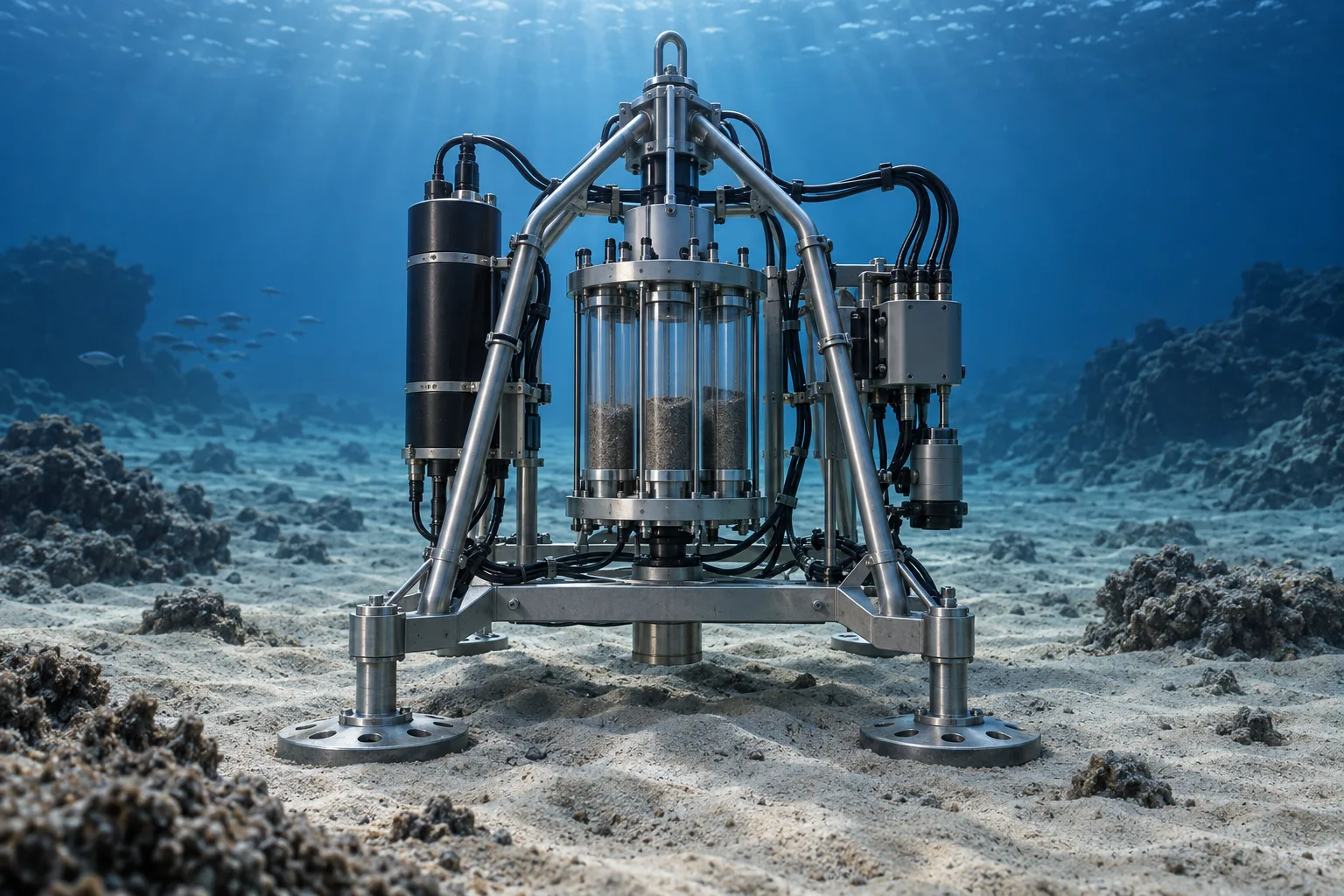
A research module returned to a docking frame
A fixed sensor can detect a target as the module reaches the docking position. If latch engagement also matters, use a separately defined sensing point. The cable interface should accommodate the intended recovery and servicing procedure.
Contact us ↗From the equipment to the input.
A typical functional path. The final arrangement depends on the equipment and project specification.
- 01
Moving equipment
Indicate a defined closure or home position on a suitable target.
- 02
Target & switch
The target reaches the defined detection point.
- 03
Cable assembly
A specified connection carries the switch state.
- 04
Control input
The equipment controller interprets the agreed contact logic.
The details to resolve together.
Define the information required
Separate mechanical position, sample integrity and instrument health in the control brief.
Specify deployment duration
Long immersion and repeated pressure cycles should be included alongside maximum depth.
Plan identification and records
Agree part identification, pinout, inspection and test records for repeatable research configurations.
Bring the installation into the brief.
Share what you have. A drawing, an existing part reference or a description of the operating requirement is a useful starting point.
Contact us ↗- Equipment drawing and required switching positions
- Maximum immersion pressure, duration, temperature and media
- Target geometry, mounting space and electrical input
- Cable route, mating connector and maintenance method
Application examples describe potential arrangements, not installed DepthLink case studies. Final suitability, ratings and test requirements are agreed for the selected assembly.
What needs to be confirmed?
Sampling mechanisms
Indicate a defined closure or home position on a suitable target.
Instrument docking
Detect local engagement or a capture-latch position.
Deployment locks
Report a locking member’s position before or after a deployment action.
Before you specify.
Does a closure indication prove a sample was collected?
No. It confirms only the specified mechanical switching point. Sample collection and retention need their own verification.
Can the cable length and instrument interface be configured?
Provide the required length, route, connector reference and wiring diagram so a complete assembly can be reviewed.
See the complete connection.
Explore how DepthLink position switches, underwater cable assemblies and custom equipment interfaces work together. Contact our team to discuss your installation.
Explore system engineering ↗