
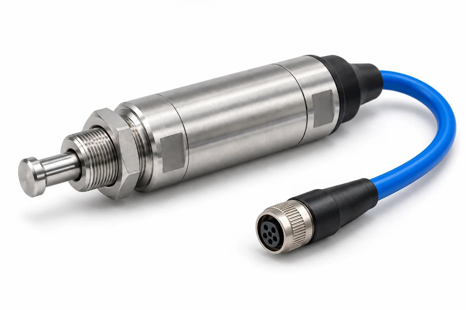
Illustrative configuration with subsea termination. Final dimensions and interfaces follow the agreed drawing.
Subsea Mechanical Limit Switch
CONFIGURED TO YOUR APPLICATIONDirect plunger actuation for end-position feedback on subsea actuators, latches and submerged machinery. Develop the switch, mounting arrangement and Nano subsea cable connection as one assembly.
Why choose this configuration?
Consider when the mechanism can deliberately actuate a plunger and allow for its operating travel.
- Actuation
- Axial mechanical plunger
- Installation
- Threaded mounting nose with adjustable locknut
Choose the mounting and connection around the mechanism, then match the electrical and immersion duty.
Compare sensing methods ↗Positive contact. Defined end position.
A cam or moving stop depresses the plunger at a defined point in the mechanism’s travel. The electrical contact changes state, then resets as the mechanism moves away.
01 / Free position
Confirm the unactuated contact state and plunger return behaviour.
02 / Operating point
Define the travel and force at which the contact changes state.
03 / Overtravel & reset
Allow the permitted additional travel, then confirm the release point on return.
Specify the assembly.
Resolve every interface.
Provide a separate mechanical stop. The switch plunger must not absorb the mechanism’s full stopping load; side loads and cam geometry need review.
Key engineering inputs
- Operating travel and force at the required pressure
- Permitted overtravel, total stroke and reset differential
- Cam alignment, return action and cycle duty
- Contact load, circuit protection and required switching function
No pressure, electrical or functional-safety certification is implied by this overview.
| Configuration | Configuration by enquiry; ratings and dimensions confirmed for the agreed assembly |
|---|---|
| Actuation | Axial mechanical plunger |
| Installation | Threaded mounting nose with adjustable locknut |
| Service environment | Subsea immersion; specify hydrostatic pressure, duration, media and temperature |
| Electrical interface | Contact function and switching / carrying loads agreed for the control circuit |
| Cable & connector | Sealed moulded cable with Nano subsea termination; mating pair and pin allocation to agree |
| Wetted materials | Stainless steel, titanium, Inconel or Monel subject to design and duty review |
| Verification | Agree pressure, insulation and functional cycling tests with acceptance criteria |
Where this configuration fits.
Actuator end positions
Confirm a defined open or closed position from physical contact with the actuator mechanism.
Review the application ↗Submerged gates & lifts
Monitor a repeatable travel limit with allowance for debris, misalignment and overtravel.
Review the application ↗Subsea latches & tooling
Confirm a mechanism reaches its intended position before the system proceeds.
Review the application ↗One coordinated
engineering brief.
Review wetted materials, static seals, mounting and cable construction together. Titanium, Inconel and Monel options require an agreed grade and evaluation of the complete design.
Specify the exact Nano mating pair and pin allocation. A connector’s immersion rating does not automatically establish the switch assembly rating or permit underwater mating.
Explore material options ↗From switch to control system
- Subsea switch housing and actuation interface
- Sealed cable exit and strain relief
- Custom cable length, conductors and jacket
- Nano subsea connector and mating assembly
- Agreed inspection, test scope and documentation
Tell us how it needs to work.
Contact our team to discuss your application, pricing and lead time.