
A valve command is only the beginning. Position feedback completes the picture.
From the moving target to the subsea control interface, every connection contributes to useful valve-position information.
An instruction to open or close a valve describes what the system should do. A switch at the actuator provides a separate indication that a defined position has been reached. On subsea equipment, that indication must travel through an assembly exposed to water, pressure and the practical demands of installation.
The sensing position, mounting bracket, connector and cable should therefore be considered together. A well-defined interface makes it easier to install the assembly, interpret the signal and plan replacement without disturbing more equipment than necessary.
Choose the feedback your equipment needs.
For subsea valve monitoring, start with the task below. These routes narrow the product search; the final configuration is reviewed against your installation and operating conditions.
Confirm valve endpoints
Sense the valve-linked member at open and closed positions. Actuator travel alone does not prove flow isolation.
Resolve together: Lost motion, target alignment and the required valve state.
Compare proximity switches ↗Detect physical actuation
Where a cam or moving feature can press a plunger, review a mechanical limit switch as another sensing method.
Resolve together: Operating force, travel, overtravel and a separate mechanical stop.
Explore mechanical limit switches ↗Connect the sensing point
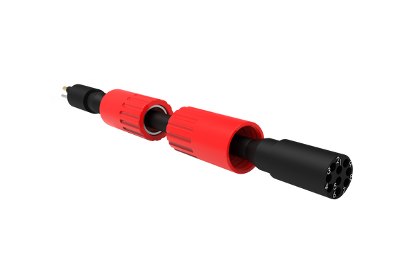
Define the lead between the sensor and equipment interface, including any movement and maintenance access.
Resolve together: Mating parts, pin allocation, cable length, routing and end termination.
Explore cable assemblies ↗Where each component fits.
Confirm a defined valve position.
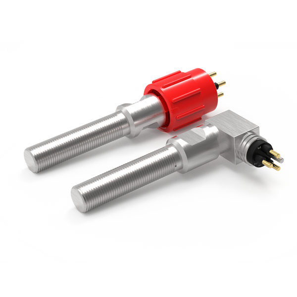
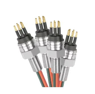
Proximity switches can indicate an open, closed or other specified travel position when the actuator moves a suitable target into the sensing zone. Two independently positioned switches may be used where separate end-position indications are required.
- Target material, shape and approach direction
- Switching gap across mounting tolerances
- Contact arrangement and control input requirements
Provide a serviceable electrical interface.
A connector separates the switch or local harness from the wider installation. Its position matters: the interface must be accessible with the intended tooling and suited to the environment in which it will be connected or disconnected.
- Wet-mate or dry-mate operating requirement
- Pin allocation, keying and contact gender
- Mating access, sealing and pressure boundary
Carry the indication back to control.
A local cable assembly links the switch to a junction point or control interface. Routing needs to accommodate the actuator envelope while protecting the termination from tension, abrasion and repeated movement.
- Conductor allocation and cable length
- Clamps, bend radius and strain relief
- Continuity, insulation and identification checks
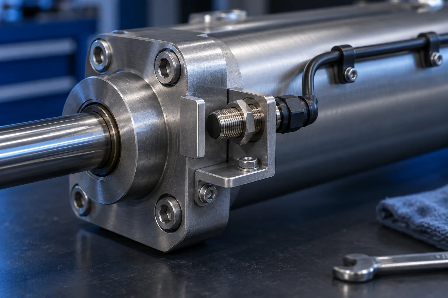
Example: separate open and closed indications
Two switches mounted around the actuator travel can feed separate control inputs through a local harness. The brief should identify which contact state represents each position, how the targets move and where the harness connects to the existing equipment.
Contact us ↗From the equipment to the input.
A typical functional path. The final arrangement depends on the equipment and project specification.
- 01
Valve movement
The actuator moves a defined target.
- 02
Position switch
The target reaches the agreed switching point.
- 03
Local assembly
Cable and connector carry the electrical indication.
- 04
Control input
The control system interprets the configured state.
The details to resolve together.
Position is not proof of sealing
An end-position indication does not, by itself, demonstrate valve leak-tightness or process isolation. Define exactly what the signal represents.
Allow for the installed geometry
Bracket tolerances, target alignment and access for adjustment can matter as much as the nominal switch dimensions.
Specify the whole environment
Confirm operating pressure, temperature, exposed materials, mating conditions and the required inspection scope for the complete assembly.
Bring the installation into the brief.
Share what you have. A drawing, an existing part reference or a description of the operating requirement is a useful starting point.
Contact us ↗- Valve and actuator arrangement or mounting drawing
- Open / closed indication and contact logic
- Target details and available installation space
- Connector reference, cable route and required length
Final ratings, switching behaviour and verification requirements are agreed for the selected assembly.
See the complete connection.
Explore how DepthLink position switches, underwater cable assemblies and custom equipment interfaces work together. Contact our team to discuss your installation.
Explore system engineering ↗