Position feedback for Lifts & Platforms
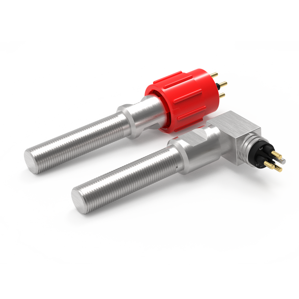
Underwater end-position sensing for submerged lifts, boat platforms and movable pool floors, including locking feedback and moving cable requirements.
Submerged lifting equipment needs to identify positions such as lowered, docked or mechanically locked. Depending on the lift design, a switch can observe a target on the platform, guide or locking member while remaining below the waterline.
Applications to review include boat-handling platforms, yacht equipment, test-basin lifts and movable pool floors. These mechanisms differ in travel, water chemistry and control requirements. The complete installation must be assessed; a position switch alone is not a lift safety system.
Choose the feedback your equipment needs.
For submerged lifts & moving platforms, start with the task below. These routes narrow the product search; the final configuration is reviewed against your installation and operating conditions.
Confirm platform and lock positions
Distinguish upper or lower travel from engagement of the locking mechanism.
Resolve together: Structure deflection, target alignment and moving-cable clearance.
Compare proximity switches ↗Detect physical actuation
Where a cam or moving feature can press a plunger, review a mechanical limit switch as another sensing method.
Resolve together: Operating force, travel, overtravel and a separate mechanical stop.
Explore mechanical limit switches ↗Connect the sensing point
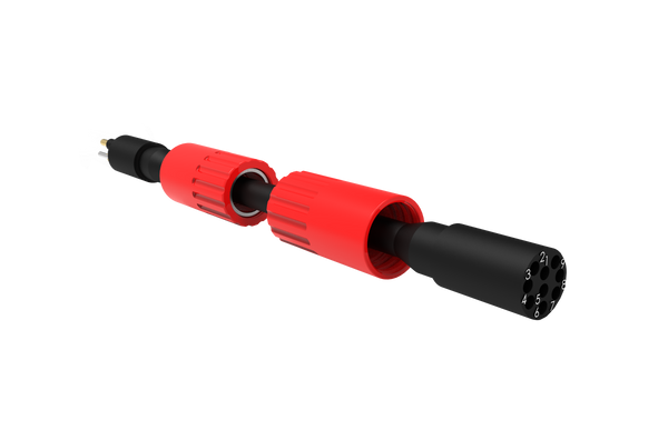
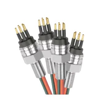
Define the lead between the sensor and equipment interface, including any movement and maintenance access.
Resolve together: Mating parts, pin allocation, cable length, routing and end termination.
Explore cable assemblies ↗Where each component fits.
Detect the defined mechanical position.
Check target movement through the complete stroke, including platform tilt and guide clearance. Select the detection point around the mechanism’s actual tolerances.
- Platform end positions
- Mechanical locks
- Retractable equipment
Make the service interface practical.
Keep the connector out of pinch points and provide sufficient access for removal. Specify freshwater, chlorinated pool water or seawater exposure.
- Exact mating reference and pin allocation
- Connection and disconnection conditions
- Access for inspection and replacement
Protect the route back to control.
Identify whether the cable flexes on every lift cycle. Travel, bend radius, restraint and cycle duty need review alongside immersion.
- Installed route and required length
- Fixed or moving duty
- Materials, restraints and termination details
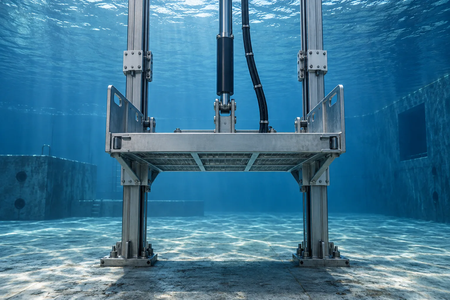
A lift with a separate docking lock
The platform can reach its docking point before its mechanical lock engages. Separate switches can distinguish these conditions. Cable routing must remain controlled over the full stroke and avoid introducing load into the switch termination.
Contact us ↗From the equipment to the input.
A typical functional path. The final arrangement depends on the equipment and project specification.
- 01
Moving equipment
Detect a target at the agreed upper, lower or docking position.
- 02
Target & switch
The target reaches the defined detection point.
- 03
Cable assembly
A specified connection carries the switch state.
- 04
Control input
The equipment controller interprets the agreed contact logic.
The details to resolve together.
Separate limit feedback from protection
Any personnel protection or lifting interlock requires equipment-level design and validation.
Consider uneven movement
A single target may not reveal platform skew. Identify what each sensor can and cannot observe.
Include the maintenance state
Explain how a failed assembly can be reached when the platform is submerged or stopped mid-travel.
Bring the installation into the brief.
Share what you have. A drawing, an existing part reference or a description of the operating requirement is a useful starting point.
Contact us ↗- Equipment drawing and required switching positions
- Maximum immersion pressure, duration, temperature and media
- Target geometry, mounting space and electrical input
- Cable route, mating connector and maintenance method
Application examples describe potential arrangements, not installed DepthLink case studies. Final suitability, ratings and test requirements are agreed for the selected assembly.
What needs to be confirmed?
Platform end positions
Detect a target at the agreed upper, lower or docking position.
Mechanical locks
Provide an indication that a locking pin or latch has reached its defined position.
Retractable equipment
Identify deployed or stowed positions on submerged lifting mechanisms.
Before you specify.
Can a switch detect both the platform and its locking pin?
They are separate mechanical conditions and generally need separate sensing points if both must be confirmed.
Does a static underwater cable suit a moving lift?
Not necessarily. Continuous immersion and repeated flexing are different duties; both need to be specified for a moving cable assembly.
See the complete connection.
Explore how DepthLink position switches, underwater cable assemblies and custom equipment interfaces work together. Contact our team to discuss your installation.
Explore system engineering ↗