
Hydracon submersible limit switch alternatives
Specify a DepthLink mechanical limit-switch solution for underwater end-of-travel or mechanism-position feedback. Send the installed Hydracon part number and drawing to start a practical replacement review.
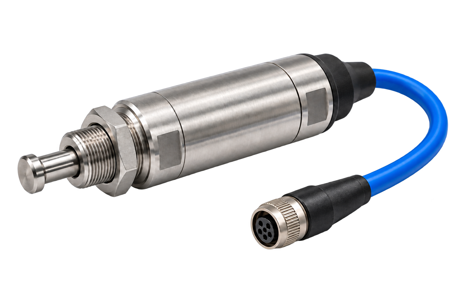
Define the mechanical travel before choosing the switch.
Hydracon lists distinct underwater limit-switch configurations, including the 1812-100 and dual-contact designs. Mechanical travel, contact arrangement and termination differ between configurations; an alternative must address the exact installed unit.
Actuation geometry
Provide the plunger direction, operating point, total stroke, permitted overtravel and mounting dimensions. Include side loads or mechanical stops in the installation drawing.
Contact duty
Record the contact arrangement, normal state, voltage and load type. Switching current, carrying current and inductive duty are separate requirements.
Cable or oil-filled termination
Identify a moulded underwater cable or pressure-balanced oil-filled (PBOF) interface. A PBOF replacement needs a specific interface review; it is not interchangeable with a standard cable exit.
Compare the installed requirement with the proposed solution.
Use these six checks to identify what can stay and what needs changing. These are selection routes, not verified part-for-part equivalents.
| Selection point | Record from the installed equipment | DepthLink route and practical difference |
|---|---|---|
| Sensing action | Plunger direction, working travel, overtravel and reset. | Mechanical limit-switch route: the mechanism must operate the plunger within the agreed travel. |
| Mounting envelope | Thread and pitch, mounting drawing, sensing-face location and space for mating and removing the cable. | Select the body and connector together. A similar thread diameter does not establish identical fit or sensing position. |
| Electrical output | NO, NC or changeover contacts; voltage, switching load and required normal state. | Agree the contact function and load for the mechanical configuration; retain the required control logic. |
| Connector and wiring | Exact mating-half reference, keying, contact arrangement, pin functions, sealing and cable termination. | Nano, Micro Straight, Micro 90° and Circular describe distinct interfaces. Review the actual mating pair and pinout; matching pin count alone is insufficient. |
| Wetted materials | Body, connector shell, mounting, target carrier, cable jacket and seal requirements. | Review the complete wetted assembly against seawater exposure and neighbouring materials. A connector material does not describe the whole switch body. |
| Pressure and immersion | Operating pressure/depth, temperature, continuous immersion and any required test evidence. | Specify the required duty for the proposed mechanical assembly; no numerical rating is transferred from the installed product. |
Physical actuation + end position
Explore the mechanical limit-switch route where a moving mechanism can operate a plunger.
Explore mechanical feedback ↗Still choosing the sensing action?
Compare physical actuation and non-contact magnetic-target sensing before selecting the mounting and cable.
Read the selection guide ↗Model numbers & configuration references
Looking for an alternative to one of these references? Send the full part number and drawing to DepthLink with your enquiry. We will assess the sensing action, mounting, electrical output and subsea connection together.
| Reference | Reference type | What to identify | Next step |
|---|---|---|---|
| 1801-201 | Published model / part reference | Limit-switch drawing reference listed in the technical index. | Assess this reference ↗ |
| 1802-100 | Published model / part reference | Dual-contact limit switch; drawing identifies -1 and -2 configurations, with NO or NC availability. | Assess this reference ↗ |
| 1812-100 | Published model / part reference | Limit-switch model with PBOF or moulded cable options. | Assess this reference ↗ |
| 1812-400 | Published model / part reference | Limit-switch/cable assembly; terminal sealing forms part of the supplied assembly. | Assess this reference ↗ |
| 1800-201 | Published model / part reference | Proximity switch with lead-wire termination. | Assess this reference ↗ |
| 1800-202 | Published model / part reference | Proximity switch with specified-length moulded cable. | Assess this reference ↗ |
| 1899-100 | Target accessory | Optional magnet actuator. | Assess this reference ↗ |
| 1899-101 | Target accessory | Optional magnet actuator. | Assess this reference ↗ |
Model families, connector suffixes and accessories are identified separately from complete switch part numbers. Custom configurations are not exhaustively listed. Inclusion does not imply a drop-in replacement or transfer any competitor rating to a DepthLink product.
A DepthLink solution around your equipment.
Mechanical limit switches
Physical actuation for underwater end-position feedback.
View product ↗Subsea cable assemblies
Define connector format, pin allocation, cable length and equipment termination.
Explore cabling ↗Configured materials & interfaces
Review stainless steel, titanium and other specified alloys for the actual assembly.
Material options ↗Relevant underwater applications
Before choosing an alternative
Is the DepthLink mechanical limit switch a drop-in 1812-100 replacement?
No drop-in equivalence is claimed. Share the exact Hydracon drawing, actuation requirements and circuit so we can define the DepthLink configuration and any installation changes.
Can material and cable options be customised?
Discuss the exact alloy, connector, cable length and termination required. DepthLink reviews these together with the mechanism and environmental duty before defining the supply configuration.
DepthLink is an independent supplier. Hydracon names identify the existing equipment or requirement; no affiliation, endorsement or automatic interchangeability is implied.
Send us the reference. Tell us what must stay.
Include the part number, drawing or datasheet, required quantity and delivery date. Tell us which mounting, target, connector and control-system interfaces need to remain unchanged.