Position feedback for Aquaculture Equipment
Explore position feedback for submerged aquaculture gates, handling equipment and locks, with connectors and cables specified for service access.
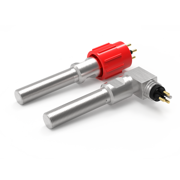
Aquaculture equipment manufacturers may need feedback from submerged gates, handling mechanisms and locking members. A position switch can indicate when a defined target reaches the required location on equipment designed to accept local sensing.
This is an equipment-specific application rather than a single standard farm installation. Describe the mechanism and maintenance method first. DepthLink can then review the target, switch, connection and cable route against the immersion and movement conditions.
Choose the feedback your equipment needs.
For aquaculture equipment position monitoring, start with the task below. These routes narrow the product search; the final configuration is reviewed against your installation and operating conditions.
Confirm a defined position
Review non-contact proximity switching for an open, closed, home or engaged indication.
Resolve together: Target geometry, sensing gap, mounting and required contact state.
Compare proximity switches ↗Detect physical actuation
Where a cam or moving feature can press a plunger, review a mechanical limit switch as another sensing method.
Resolve together: Operating force, travel, overtravel and a separate mechanical stop.
Explore mechanical limit switches ↗Connect the sensing point
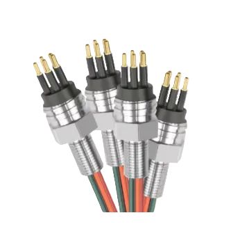
Define the lead between the sensor and equipment interface, including any movement and maintenance access.
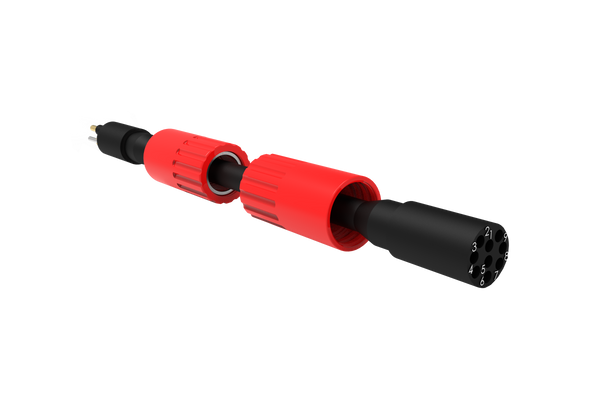
Resolve together: Mating parts, pin allocation, cable length, routing and end termination.
Explore cable assemblies ↗Where each component fits.
Detect the defined mechanical position.
Consider biofouling and access for inspection when locating the target and sensor. Agree the switching gap across structural movement.
- Handling gates
- Equipment locks
- Deployment mechanisms
Make the service interface practical.
Decide whether service crews recover the equipment before disconnecting it. That decision shapes the mating requirement and connection location.
- Exact mating reference and pin allocation
- Connection and disconnection conditions
- Access for inspection and replacement
Protect the route back to control.
Keep cables restrained and clear of nets, ropes and animal-handling paths. Include water movement and cleaning practices in the specification.
- Installed route and required length
- Fixed or moving duty
- Materials, restraints and termination details
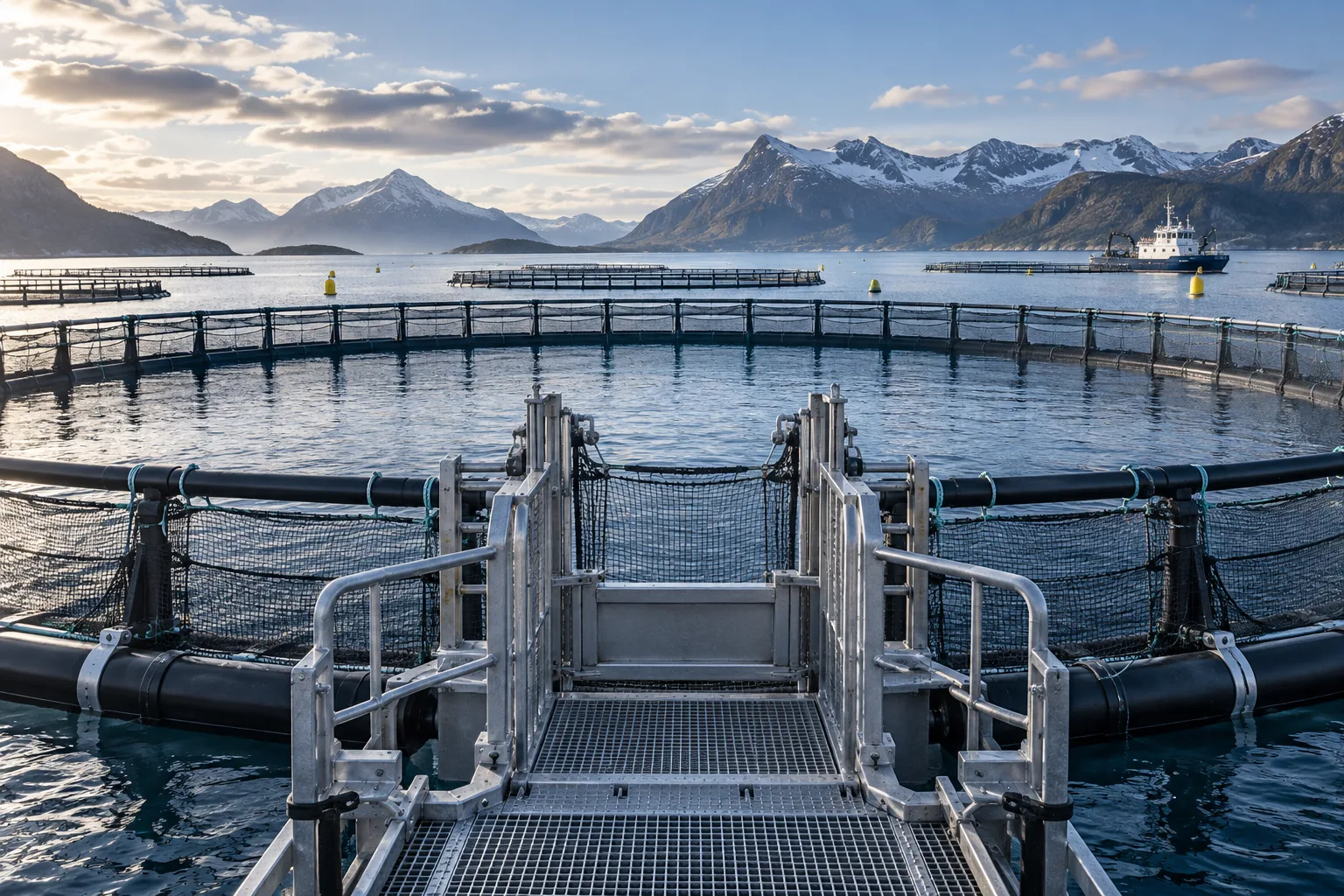
A submerged service gate
A gate designer may require separate open and closed signals. Targets and switches should be placed around the gate’s full movement and expected fouling. Routing must avoid snagging nets, lines and maintenance tools.
Contact us ↗From the equipment to the input.
A typical functional path. The final arrangement depends on the equipment and project specification.
- 01
Moving equipment
Detect a specified gate or linkage position on submerged equipment.
- 02
Target & switch
The target reaches the defined detection point.
- 03
Cable assembly
A specified connection carries the switch state.
- 04
Control input
The equipment controller interprets the agreed contact logic.
The details to resolve together.
Avoid unsupported process claims
A position indication does not establish fish welfare, containment integrity or a complete process outcome.
Account for cleaning
Identify cleaning tools and chemicals that may contact the assembly.
Specify service intervals
Describe how often the mechanism is inspected and how fouling is managed around the sensor.
Bring the installation into the brief.
Share what you have. A drawing, an existing part reference or a description of the operating requirement is a useful starting point.
Contact us ↗- Equipment drawing and required switching positions
- Maximum immersion pressure, duration, temperature and media
- Target geometry, mounting space and electrical input
- Cable route, mating connector and maintenance method
Application examples describe potential arrangements, not installed DepthLink case studies. Final suitability, ratings and test requirements are agreed for the selected assembly.
What needs to be confirmed?
Handling gates
Detect a specified gate or linkage position on submerged equipment.
Equipment locks
Indicate a defined latch or pin state on serviceable mechanisms.
Deployment mechanisms
Report home, deployed or retracted positions on moving farm equipment.
Before you specify.
Are these switches water-quality sensors?
No. This application concerns mechanical position. Oxygen, salinity and other water-quality measurements require separate instruments.
Can a switch be retrofitted to existing equipment?
Potentially, if a suitable target and protected mounting location can be provided. Send drawings and photographs for an interface review.
See the complete connection.
Explore how DepthLink position switches, underwater cable assemblies and custom equipment interfaces work together. Contact our team to discuss your installation.
Explore system engineering ↗