
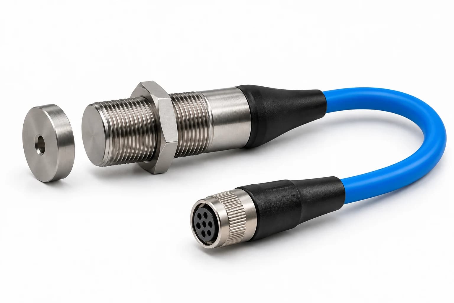
Illustrative configuration with subsea termination. Final dimensions and interfaces follow the agreed drawing.
Cable-Connected Subsea Magnetic Proximity Switch
CONFIGURED TO YOUR APPLICATIONA magnet-operated subsea proximity switch with a sealed sensing face, adjustable threaded mount and moulded cable to a Nano subsea connector. Select the target and complete cable assembly together.
Why choose this configuration?
Consider a moulded cable arrangement when you want to route the mating connection away from the sensing point.
- Actuation
- Non-contact magnetic target
- Installation
- Threaded body with adjustment locknut
Choose the mounting and connection around the mechanism, then match the electrical and immersion duty.
Compare sensing methods ↗Request CAD file ↗
Request a CAD file for Cable-Connected Subsea Magnetic Proximity Switch. Our team will follow up by email.
Position feedback. Without contact.
A separate magnetic target moves into the sensing zone and changes the contact state. There is no external moving plunger; the target, sensing gap and mounting tolerances define the operating point.
Actuate
Define how the operator, mechanism or magnetic target produces the input.
Connect
Match the contact function, cable and Nano subsea termination to the control circuit.
Verify
Test the complete configuration against the agreed immersion and operating duty.
Specify the assembly.
Resolve every interface.
This family uses a magnetic target. It is not a general-purpose inductive metal detector; sensing distance cannot be specified independently of the target and installation.
Key engineering inputs
- Magnet grade, orientation and mounting arrangement
- Operate and release gaps across installation tolerances
- Housing material and surrounding magnetic influences
- Contact load, switching rate and cable pin allocation
No pressure, electrical or functional-safety certification is implied by this overview.
| Configuration | Configuration by enquiry; ratings and dimensions confirmed for the agreed assembly |
|---|---|
| Actuation | Non-contact magnetic target |
| Installation | Threaded body with adjustment locknut |
| Service environment | Subsea immersion; specify hydrostatic pressure, duration, media and temperature |
| Electrical interface | Contact function and switching / carrying loads agreed for the control circuit |
| Cable & connector | Sealed moulded cable with Nano subsea termination; mating pair and pin allocation to agree |
| Wetted materials | Stainless steel, titanium, Inconel or Monel subject to design and duty review |
| Verification | Agree pressure, insulation and functional cycling tests with acceptance criteria |
Where this configuration fits.
Valve position feedback
Detect a magnet attached to a moving valve or actuator mechanism.
Review the application ↗Water infrastructure
Monitor submerged mechanisms where a non-contact arrangement suits the duty.
Review the application ↗Gates & submerged platforms
Allow for target movement, fouling and installation clearance.
Review the application ↗One coordinated
engineering brief.
Review wetted materials, static seals, mounting and cable construction together. Titanium, Inconel and Monel options require an agreed grade and evaluation of the complete design.
Specify the exact Nano mating pair and pin allocation. A connector’s immersion rating does not automatically establish the switch assembly rating or permit underwater mating.
Explore material options ↗From switch to control system
- Subsea switch housing and actuation interface
- Sealed cable exit and strain relief
- Custom cable length, conductors and jacket
- Nano subsea connector and mating assembly
- Agreed inspection, test scope and documentation
Tell us how it needs to work.
Contact our team to discuss your application, pricing and lead time.
Also explore our existing Nano proximity switch configurations ↗