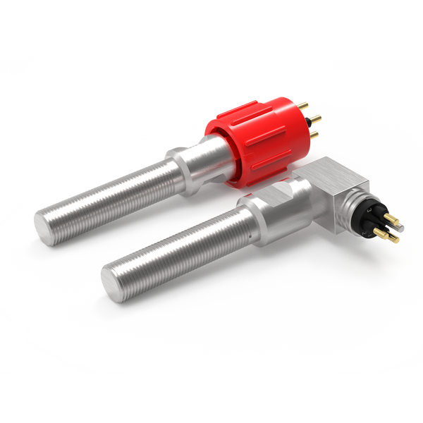

Make the movement visible to the control system.
Position switches, serviceable connectors and correctly routed cables turn actuator travel into a clear electrical indication.
Linear and rotary actuators move valves, mechanisms and tooling. A control system may need to know when the mechanism has reached an end stop, returned home or arrived at another defined position. Discrete switch feedback addresses those specific events; continuous travel measurement is a different requirement.
The physical installation determines the sensing arrangement. A target moving past a stationary switch behaves differently from one approaching the switch face, and the cable must remain clear of moving parts throughout the operating cycle.
Choose the feedback your equipment needs.
For actuator feedback systems, start with the task below. These routes narrow the product search; the final configuration is reviewed against your installation and operating conditions.
Confirm fully retracted or extended
Use separate targets at the required endpoints when the controller needs a discrete stroke indication.
Resolve together: Endpoint tolerances, contact state and independent travel stops.
Compare proximity switches ↗Follow the cylinder stroke
Review linear position feedback when the controller needs more than an end-position signal. The output follows travel in steps.
Resolve together: Stroke, resolution, output, magnet arrangement and installation envelope.
Explore linear position sensing ↗Connect the sensing point
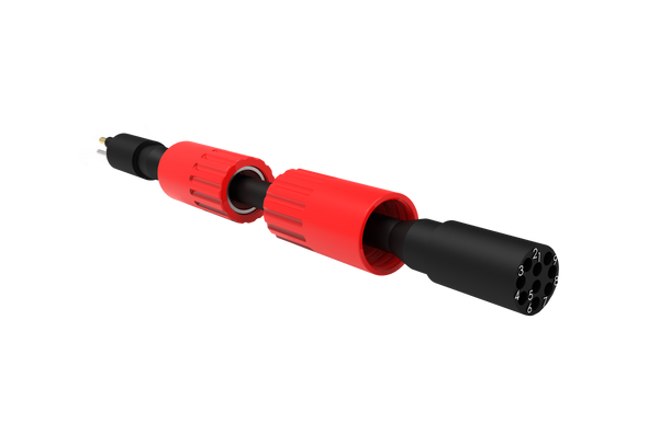
Define the lead between the sensor and equipment interface, including any movement and maintenance access.
Resolve together: Mating parts, pin allocation, cable length, routing and end termination.
Explore cable assemblies ↗Where each component fits.
Detect the position that matters.
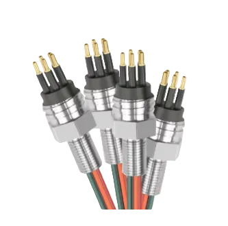
Mount a proximity switch against a defined target on the actuator or driven mechanism. For rotary motion, a flag or cam can establish a repeatable switching point; for linear motion, the target can travel past or towards the sensing face.
- Linear or rotary movement and target path
- End-of-travel or intermediate indication
- Repeatability, overtravel and adjustment access
Separate the actuator from the harness.
A local connector can make assembly replacement more manageable and avoid disturbing a long cable run. The selected interface must fit the mechanical envelope and accommodate the installation and maintenance process.
- Clearance around the mating interface
- Connection method and locking arrangement
- Signal allocation and identification
Accommodate movement without loading the termination.
Where a cable moves with the mechanism, its construction and route must suit the movement duty. Where it remains fixed, clamps and a controlled service loop can help keep it away from pinch points and exposed edges.
- Fixed or moving cable duty
- Travel envelope and bend radius
- Strain relief at the switch and connector
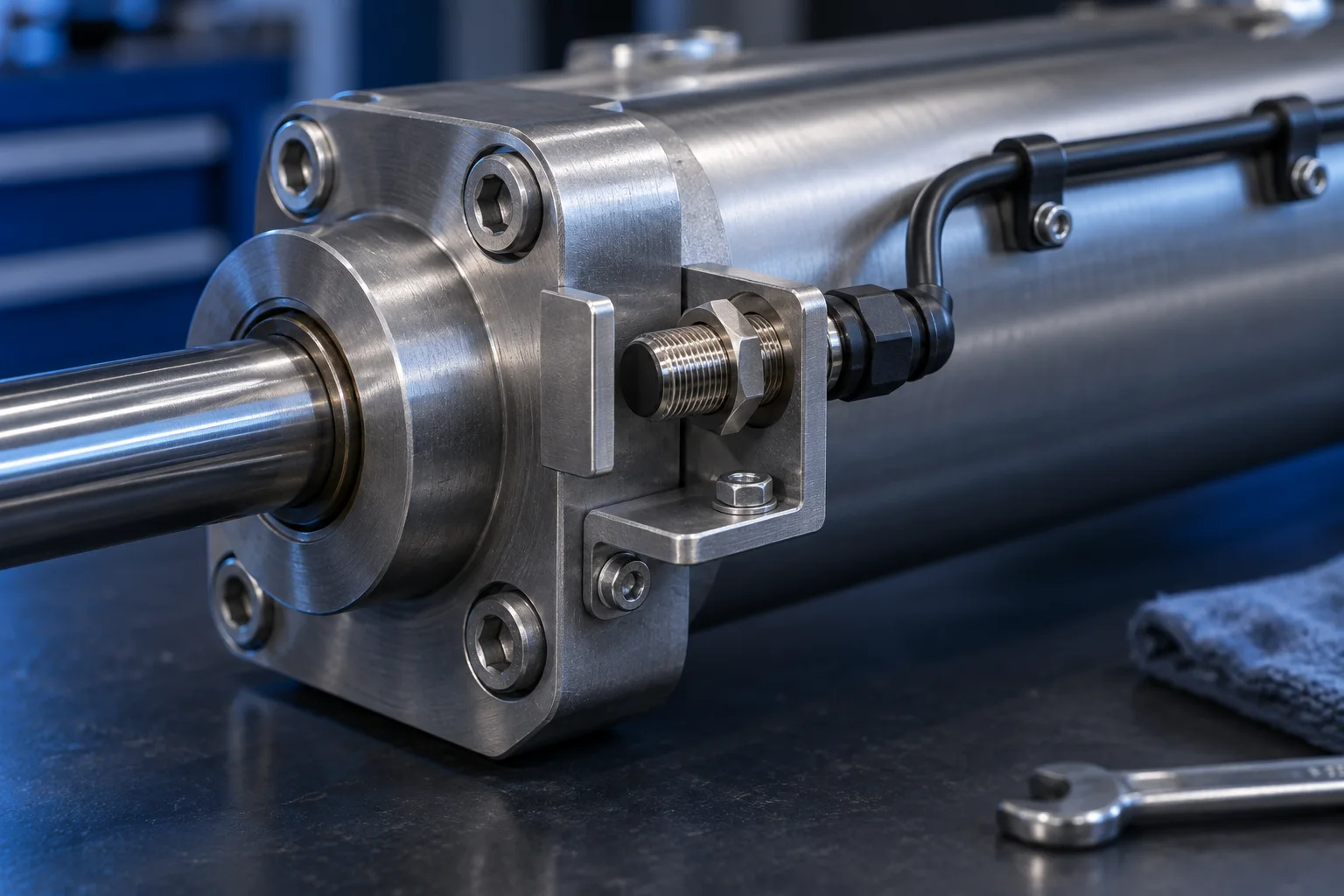
Example: a compact actuator with limited clearance
A small switch may fit the mounting pocket, yet leave too little room for connector removal or cable bending. Reviewing the sensor, mating half and first section of cable together can resolve this before the bracket or housing is finalised.
Contact us ↗From the equipment to the input.
A typical functional path. The final arrangement depends on the equipment and project specification.
- 01
Mechanism
A linear stroke or rotary movement changes position.
- 02
Target
A flag, cam or other suitable target reaches the sensor.
- 03
Switch circuit
The contact state changes at the defined position.
- 04
Equipment control
The cable assembly presents that state at the input.
The details to resolve together.
Discrete or continuous?
State whether you need an on/off position indication or a measurement over the full travel. A limit switch does not provide continuous position data.
Define the electrical behaviour
Match the contact arrangement and permitted switching load to the control input. Include any diagnostic or fault-detection requirements in the brief.
Review the complete movement
Check the cable route and switching gap through the full stroke, including normal tolerances and any permitted overtravel.
Bring the installation into the brief.
Share what you have. A drawing, an existing part reference or a description of the operating requirement is a useful starting point.
Contact us ↗- Actuator travel, motion type and mounting drawing
- Required switching positions and target geometry
- Input voltage, load and contact arrangement
- Cable movement duty, route and connector details
If feedback forms part of a safety function, identify the required assessment and evidence at the enquiry stage; a position indication alone is not a safety-system approval.
See the complete connection.
Explore how DepthLink position switches, underwater cable assemblies and custom equipment interfaces work together. Contact our team to discuss your installation.
Explore system engineering ↗