
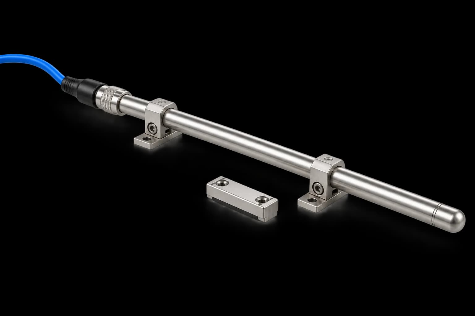
Subsea Linear Position Transmitter
Measure how far your underwater cylinder or actuator has moved.
A sensor mounted beside the cylinder detects a magnet moving with the rod, providing position feedback throughout the stroke.
Fixed sensor. Moving magnet. Position signal.
Fixed sensor, moving target
The sensor tube mounts alongside the cylinder. A magnet carrier attached to the moving rod travels beside the tube, within the agreed sensing gap.
Travel becomes a position signal
The magnet operates successive sensing elements connected to a resistive network. The electrical value changes in defined steps as the rod moves; measurement resolution depends on the selected configuration.
Connect to the control system
A suitable conditioner reads the position signal. A 4–20 mA or 0–10 V interface can be specified for review. Match the supply, pin allocation and Nano subsea cable assembly to the selected output.
Set up the installed stroke
Align the sensor and target over the full travel, set zero and span, and verify readings in both directions. Separate end-position switches may still be required for the control or safety design.
Choose a starting point. We tailor the assembly.
Select your stroke, output and materials, then send us your requirements. Mounting, cable length and final performance are agreed around your installation.
DL-LP-[STROKE]-[OUTPUT]-[MATERIAL]-N6-[CABLE]-[CONTACTS]Example: DL-LP-0500-I-SS-N6-SE-0
500 mm stroke · 4–20 mA · 316L body · Nano 6-pin · single-ended cable · no end contacts.
Options require configuration confirmation. Numerical performance figures in the technical details and datasheet are preliminary design targets, not qualified ratings.
Download the one-page specification and ordering matrix ↓Technical details.
Overall specification and design targets
Confirm the complete sensor, connector and cable assembly against the selected duty. Hydraulic cylinder pressure and external water pressure are separate requirements.
| Product status | Configuration by enquiry — numerical values below are preliminary targets pending qualification |
|---|---|
| Sensing principle | Magnet-operated sensing elements and resistive network; stepped stroke feedback |
| Measuring stroke | Target 50–2,000 mm; proposed 50 mm increments |
| Element pitch / resolution | 10 mm proposed pitch; 5 mm overlap resolution is a design objective requiring verification |
| Linearity / repeatability | Targets ±5 mm / ±2 mm; method and operating conditions to be agreed |
| Magnet gap / speed | Targets 3–15 mm / 1 m/s; verify magnet, housing and dynamic response together |
| Passive output | Proposed 3-wire ratiometric resistance; suitable signal conditioning required |
| Current output | Proposed 4–20 mA, 2-wire; 10–30 VDC target, loop budget to be confirmed |
| Voltage output | Proposed 0–10 V, 3-wire; 12–30 VDC target |
| End-position contacts | Optional 2 × Form A with shared common, subject to pin allocation and load review |
| Connection | Nano circular 6-pin; mating connector, cable and rating confirmed by configuration |
| Housing | 316L stainless steel; Inconel, titanium and Monel options by engineering review |
| Sensor tube | Proposed Ø16 mm; final dimensions and mounting drawing to be agreed |
| External pressure | 690 bar design target only — not a released or certified assembly rating |
| Temperature | Targets −40 to +85 °C passive / −20 to +70 °C conditioned; qualification required |
| Testing & documents | Agreed configuration drawing and verification plan; no test result or certification implied |
Installation, calibration and end-position switches
The sensor tube is fixed outside the cylinder, with the magnet carrier attached to the moving rod. Agree target gap, bracket positions and clearance over the full stroke, then verify zero, span and repeatability on the installed assembly.
The position output changes in defined steps. Separate end-position switches may still be needed for control or safety functions. An internal magnet arrangement requires a separate review of the cylinder wall and magnetic path.
Materials, cable assembly and Nano interface
Review housing material, magnetic response, seals, connector mating pair, pin allocation and cable length together. Material changes require configuration-specific assessment. Confirm wet or dry mating requirements for the exact connector assembly.
Tell us the stroke you need to monitor.
Send your cylinder or actuator drawing, required travel, output preference and operating conditions. We’ll help define the complete assembly.