Hydropower Gate & Valve Position Monitoring
Submerged position feedback for hydropower intake gates, isolation valves and locking mechanisms. Specify sensing, cables and connectors together.
Hydropower and pumped-storage installations use gates and valves to manage access to water passages and equipment. Where a position target remains immersed, local switching can provide a defined indication at the mechanism.
DepthLink application review focuses on the sensing assembly and its connection to the control input. Gate travel measurement, turbine control and the plant protection system are separate engineering scopes; a discrete switch does not measure the full movement of a gate.
Choose the feedback your equipment needs.
For hydropower & pumped storage, start with the task below. These routes narrow the product search; the final configuration is reviewed against your installation and operating conditions.
Confirm a defined position
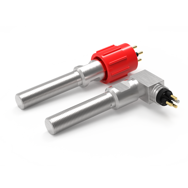
Review non-contact proximity switching for an open, closed, home or engaged indication.
Resolve together: Target geometry, sensing gap, mounting and required contact state.
Compare proximity switches ↗Detect physical actuation
Where a cam or moving feature can press a plunger, review a mechanical limit switch as another sensing method.
Resolve together: Operating force, travel, overtravel and a separate mechanical stop.
Explore mechanical limit switches ↗Connect the sensing point
Define the lead between the sensor and equipment interface, including any movement and maintenance access.
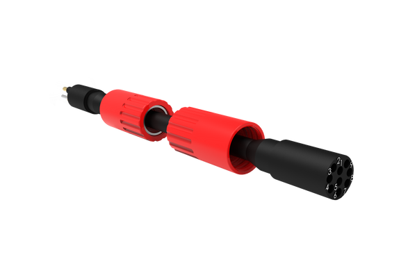
Resolve together: Mating parts, pin allocation, cable length, routing and end termination.
Explore cable assemblies ↗Where each component fits.
Detect the defined mechanical position.
Specify pressure at the actual installation point and target position across the expected gate movement. Include vibration and permitted mechanical play.
- Intake and isolation gates
- Submerged valve mechanisms
- Maintenance locks
Make the service interface practical.
Document the pressure boundary and whether the interface will be serviced wet or after dewatering. Access may determine whether a local connector or continuous cable is preferable.
- Exact mating reference and pin allocation
- Connection and disconnection conditions
- Access for inspection and replacement
Protect the route back to control.
Route cables through protected supports clear of moving equipment. Describe flow exposure, unsupported spans and the route to the plant junction point.
- Installed route and required length
- Fixed or moving duty
- Materials, restraints and termination details
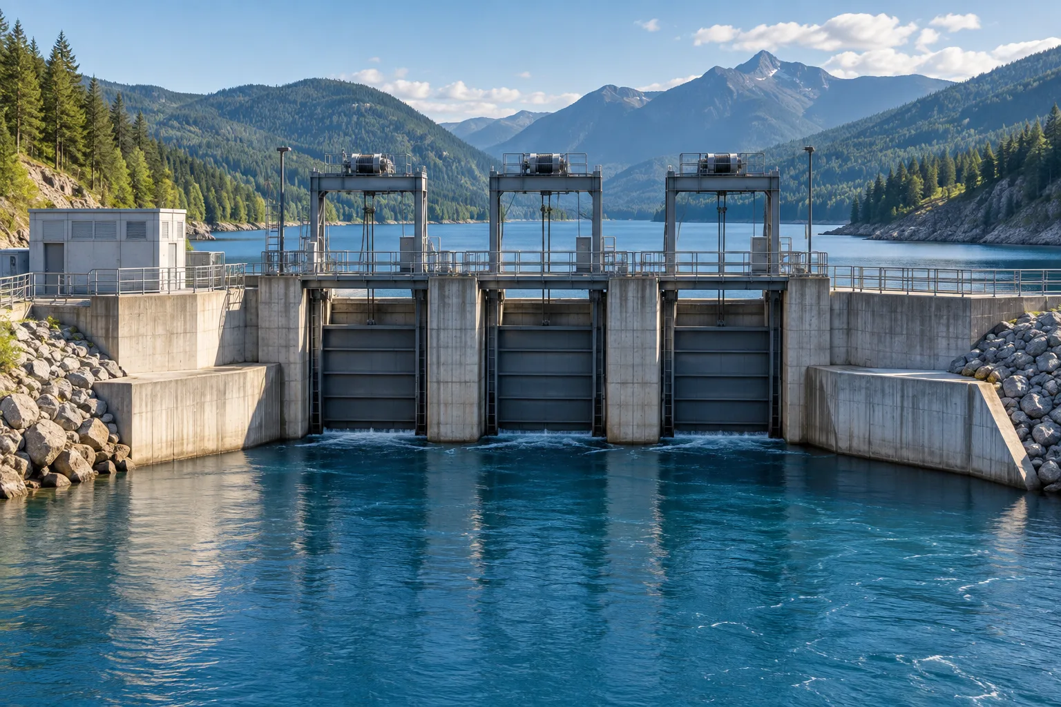
Intake-gate end-position feedback
A target on the gate may approach a fixed sensing point near the end of travel. The brief should include water head at that location, changing reservoir conditions and gate deflection. Cable routing to an accessible junction should be considered before finalising the bracket.
Contact us ↗From the equipment to the input.
A typical functional path. The final arrangement depends on the equipment and project specification.
- 01
Moving equipment
Detect defined end positions on submerged gate members or linkages.
- 02
Target & switch
The target reaches the defined detection point.
- 03
Cable assembly
A specified connection carries the switch state.
- 04
Control input
The equipment controller interprets the agreed contact logic.
The details to resolve together.
Water head is location-specific
Use the maximum pressure at the sensor rather than a general reservoir depth.
Allow for structural movement
A nominal switching gap on a drawing must remain valid across the gate’s tolerance and deflection envelope.
Agree acceptance evidence
Define functional, electrical and pressure-test requirements for the supplied assembly.
Bring the installation into the brief.
Share what you have. A drawing, an existing part reference or a description of the operating requirement is a useful starting point.
Contact us ↗- Equipment drawing and required switching positions
- Maximum immersion pressure, duration, temperature and media
- Target geometry, mounting space and electrical input
- Cable route, mating connector and maintenance method
Application examples describe potential arrangements, not installed DepthLink case studies. Final suitability, ratings and test requirements are agreed for the selected assembly.
What needs to be confirmed?
Intake and isolation gates
Detect defined end positions on submerged gate members or linkages.
Submerged valve mechanisms
Indicate travel limits where the sensing point is exposed to water pressure.
Maintenance locks
Confirm a specified pin or latch position on equipment designed for local detection.
Before you specify.
Can a proximity switch measure gate opening percentage?
A discrete switch reports a defined switching position. Continuous gate opening percentage requires a suitable travel-measurement system.
What information is needed for a hydropower enquiry?
Provide gate or valve drawings, sensor location and maximum pressure, target geometry, required contact states, cable routing and the inspection requirements.
See the complete connection.
Explore how DepthLink position switches, underwater cable assemblies and custom equipment interfaces work together. Contact our team to discuss your installation.
Explore system engineering ↗