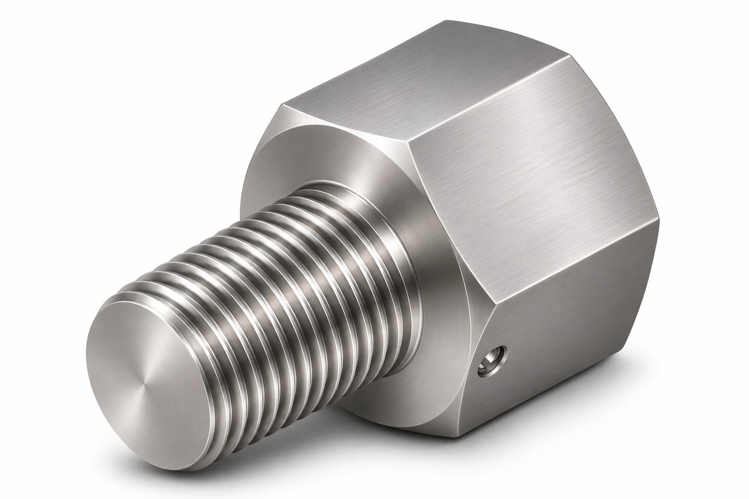
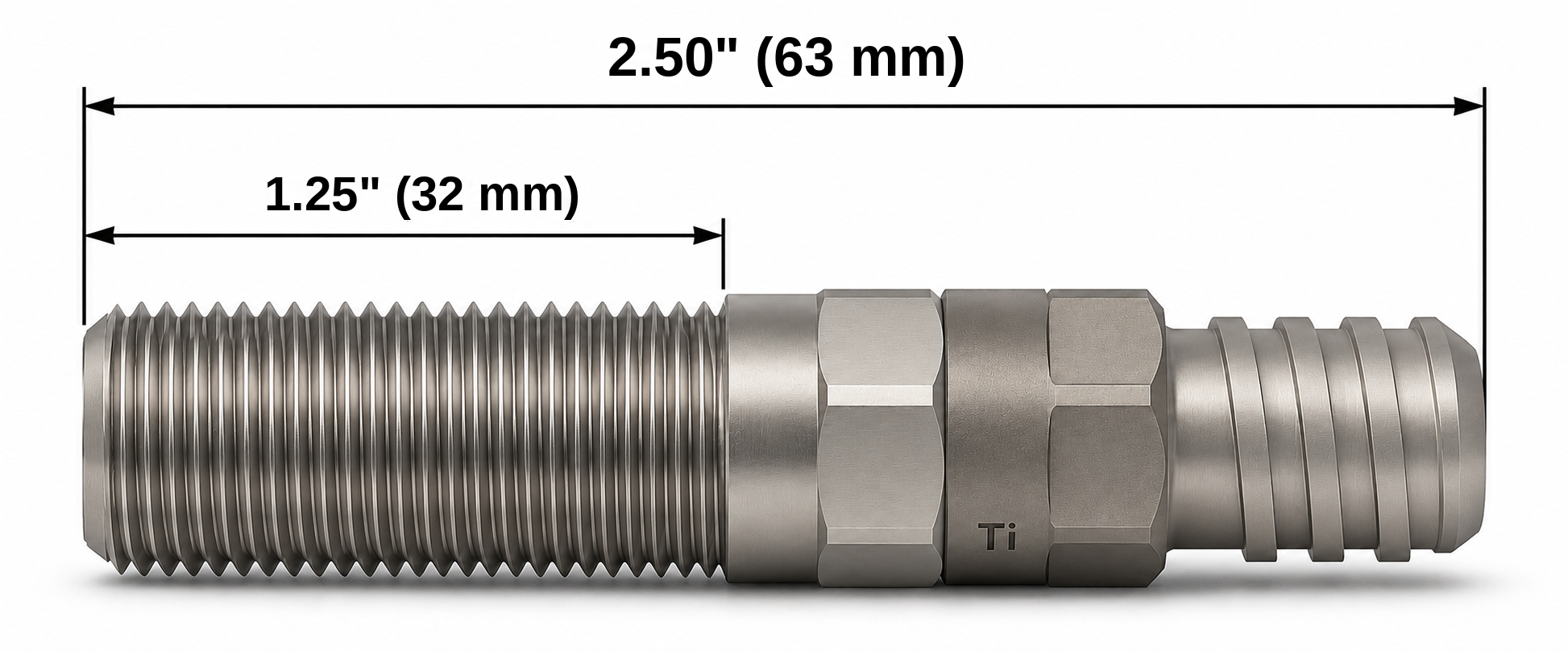
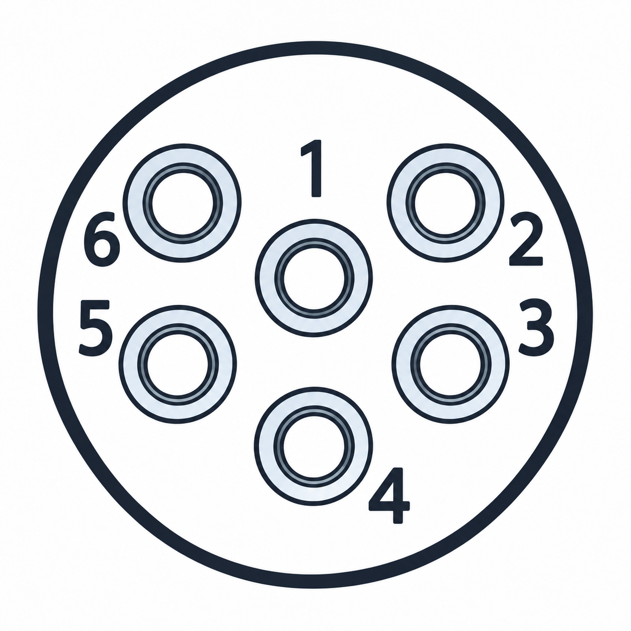
An ultra compact magnetic proximity switch for discrete position feedback on submerged equipment. The M12 × 1.0 threaded titanium body has an integral titanium Nano six-pin male subsea connector. Volt-free SPDT contacts change state when the optional MT-01 target magnet approaches within the specified 5/8" (16 mm) sensing range. Supplied as a switch; order the target and mating cable separately.
DEPTH RATING10,000 PSIApprox. 690 bar · Approx. 6,900 m seawater
Small footprint. Subsea position feedback.
Our ultra-compact switch platform combines an M12 mounting thread with an integrated Nano subsea connector. Choose it when mounting space and connector clearance are limited. Micro and Nano refer to connector families, independently of the mounting thread.
Connector Type
Nano connector
Contact Form
SPDT changeover
Connector mating
Wet-mateable
Choose the mounting and connection around the mechanism, then match the electrical and immersion duty.
Agree inspection, electrical testing, pressure testing and supporting records as part of your quotation.
TESTED TO
Proven before it goes subsea.
Rated for continuous submersion. Every DepthLink proximity switch is tested at multiple stages of manufacture.
1.5×Depth-pressure proof test
Tested to 1.5× the certified depth pressure rating for the configuration.
100%Production testing
Every switch is tested at multiple manufacturing stages before release.
10⁸Mechanical cycles
Rated to 100 million mechanical operations.
3×10⁶Cycles at maximum load
Rated operations at the maximum specified switching load.
Additional depth testing, witnessed tests and supporting test records can be agreed to your project requirements. Discuss test requirements ↗
NANO M12 / INSTALLATION BRIEF
Small switch. Plan the whole installation.
The M12 mounting thread describes the switch body, not the space needed for the complete connected assembly. Use the dimensional drawing to plan the sensing point, then allow for the mating connector and cable route.
01 / Allow for the connection
Check the threaded mounting length, locknut access and clearance behind the Nano connector. Include the mating plug, cable bend and room to connect or disconnect the assembly. A short sensor body alone does not establish the installed envelope.
02 / Position the magnetic target
Specify the target magnet and approach direction with the operating gap. Check the closest and furthest target positions, mounting tolerances and nearby ferrous parts. Verify the switching and release points on the mechanism before setting the final stops.
03 / Specify the immersion duty
Give the maximum working depth, pressure, water temperature and immersion duration. Check the selected switch reference, mating cable and termination against that duty. Wet-mate capability describes the interface; use its supplied mating procedure and operating limits.
A useful enquiry includes
Switch reference · mounting drawing · target and operating gap · maximum depth · contact load · cable length and termination · quantity.
Fix the switch beside the mechanism and mount the specified target on the moving part. The target passes the sensing face at the position you need to detect.
Target enters the sensing range
The suitable target changes the configured contact state without physically pressing the switch. Confirm the target type, sensing gap and alignment against the exact product drawing.
Connect the position signal
Route the signal through this product’s specified cable and connector arrangement to the control input. Review the contact function, electrical load and pin allocation together.
Check travel and repeatability
Verify indication and reset throughout the installation tolerances. A proximity switch indicates a defined position; it does not measure the entire cylinder stroke.
For this product: Use the approved configuration for Subsea Proximity Switch - M12 Thread - Titanium - Nano. Confirm mounting thread, target, sensing gap, body and connector materials, cable route and operating conditions.
This is a subsea switch configuration. Specify continuous immersion as an operating duty, including external pressure, duration, water temperature and media. The supplied assembly specification defines its limits, including the actuation interface and cable termination.
What should I specify for use in seawater?
Specify the water conditions and the materials of the housing, connector, mounting hardware and target or striker. Material selection is specific to the installation; a corrosion-resistant housing does not establish the suitability of every connected component.
What target does the switch detect?
Select the target and operating gap for this configuration. A proximity switch indicates a defined position; it does not measure the complete travel of an actuator. Use the product drawing to establish the target, approach direction and mounting clearance.
Need help choosing a subsea proximity switch?
Tell us the application, operating depth and quantity, if known. We’ll help with the configuration, price and lead time.
Underwater position feedback, configured for your equipment.
Selecting a subsea proximity switch or submersible position sensor starts with the duty: valve position, actuator travel, gate position or tool engagement. Review the sensing target, mounting, switching load and operating conditions alongside the cable assembly.