
Small connections support a much larger offshore asset.
Instrumentation, underwater inspection and auxiliary equipment depend on clear signal paths around foundations and offshore structures.
An offshore wind installation contains more than its main power transmission system. Monitoring instruments, inspection equipment and auxiliary mechanisms also need electrical connections suited to their location, servicing method and exposure to the marine environment.
These interfaces may sit underwater, in a splash-exposed area or inside protected equipment. Identifying the actual environment prevents a generic “offshore” description from hiding the details that determine the switch, connector and cable arrangement.
Choose the feedback your equipment needs.
For offshore wind, start with the task below. These routes narrow the product search; the final configuration is reviewed against your installation and operating conditions.
Confirm a defined position
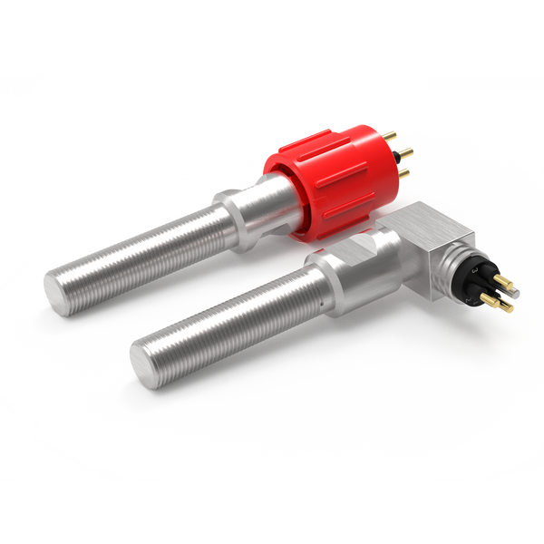
Review non-contact proximity switching for an open, closed, home or engaged indication.
Resolve together: Target geometry, sensing gap, mounting and required contact state.
Compare proximity switches ↗Detect physical actuation
Where a cam or moving feature can press a plunger, review a mechanical limit switch as another sensing method.
Resolve together: Operating force, travel, overtravel and a separate mechanical stop.
Explore mechanical limit switches ↗Connect the sensing point
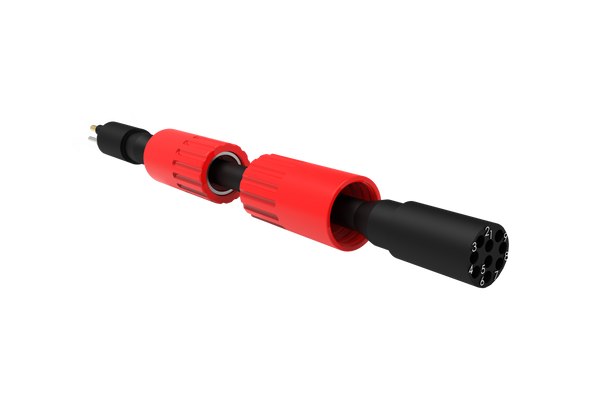
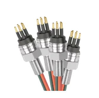
Define the lead between the sensor and equipment interface, including any movement and maintenance access.
Resolve together: Mating parts, pin allocation, cable length, routing and end termination.
Explore cable assemblies ↗Where each component fits.
Confirm auxiliary mechanism positions.
Position switches can be considered on suitable submerged or exposed auxiliary mechanisms where a defined open, closed or travel state is required. Their role is discrete position feedback, separate from the wider structural or environmental monitoring instruments.
- Defined mechanism and target position
- Mounting access and adjustment
- Signal requirements and local exposure
Make instrument interfaces serviceable.
A connector can provide a removal point for a monitoring device, local lead or inspection package. Decide whether connection takes place underwater or after recovery, and specify the exact mating interface accordingly.
- Fixed monitoring or temporary inspection package
- Mating conditions and maintenance access
- Contact allocation and instrument interface
Protect the local instrumentation route.
Instrumentation leads connect devices to a local junction or acquisition interface. A fixed foundation route and a moving cable on floating equipment have different demands; the cable construction, protection and supports must reflect the installation.
- Fixed routing or defined movement duty
- Abrasion protection, clamps and bend limits
- Screening, conductor allocation and termination
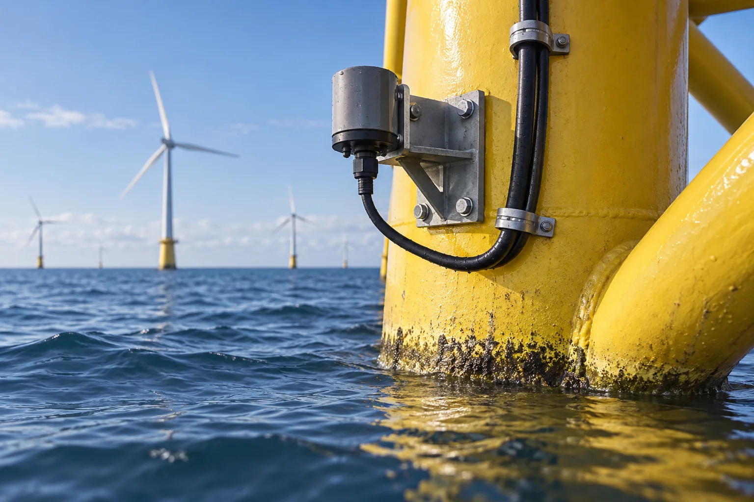
Example: a retrievable monitoring instrument
A foundation-mounted device may need periodic removal. Locating the connector and cable restraints around the maintenance method can make that task more straightforward. The brief should distinguish a connection made underwater from one made only after the equipment has been recovered.
Contact us ↗From the equipment to the input.
A typical functional path. The final arrangement depends on the equipment and project specification.
- 01
Device
An instrument or position switch produces information.
- 02
Local lead
A protected cable carries its electrical signal.
- 03
Service interface
A connector provides the agreed connection point.
- 04
Acquisition system
The local system collects the information.
The details to resolve together.
Specify the exposure zone
Describe continuous immersion, splash exposure, temperature and maintenance conditions rather than relying on an offshore label.
Separate signal and power scopes
This application discussion concerns local sensing and instrumentation connections. Array and export power cables require their own specialist design and qualification.
Consider lifetime access
Include how the instrument is reached, disconnected and replaced, plus any movement or handling loads expected during service.
Bring the installation into the brief.
Share what you have. A drawing, an existing part reference or a description of the operating requirement is a useful starting point.
Contact us ↗- Instrument or auxiliary mechanism and its location
- Immersion / splash conditions and maintenance method
- Signal type, connector references and cable route
- Fixed or moving duty and required documentation
Product selection and suitability are reviewed against the specific monitoring or auxiliary-equipment requirement.
See the complete connection.
Explore how DepthLink position switches, underwater cable assemblies and custom equipment interfaces work together. Contact our team to discuss your installation.
Explore system engineering ↗